Upper Steer-by-Wire Electrical Subsystem
The original unmodified go-kart platform uses an alloy shaft to connect the steering wheel and the front wheel. Steering is made possible entirely through the driver’s torque input. In order to provide an autonomous mode, a motor must be added to actuate the steering. Several design ideas have been composed: one attempt was to mount the motor parallel to the steering shaft and use a belt or chain for motion transmission.
Upper Steer-by-Wire
The USbW is a unique PCB mounted near the steering column. This module controls the go-kart’s steering mechanism. The USbW’s Nucleo receives the desired steering angle from the CAN bus and sends out the current steering position. Angle measurement is done using a rotary encoder fitted directly to the steering shaft. Steering control is implemented using a closed-loop PID control. The Nucleo outputs a PWM signal to the motor controller. An additional feature is the manual override, allowing the driver to take over steering control instantly. This feature uses a toggle switch and bypasses the electronic system, ensuring safety in the event of an electronic malfunction.
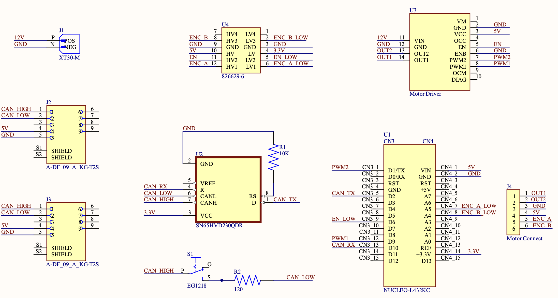
img1: schematic of upper-steer-by-wire
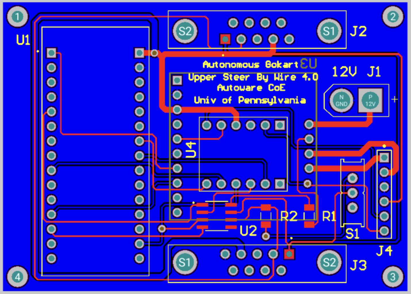
img2: PCB of upper-steer-by-wire
Code Structure Overview
Introduction The software is tailored for STM32 microcontrollers, acting as the brain of an Upper Steer-by-Wire system. It processes steering instructions received from the CAN bus, calculates the current steering angle, and sends feedback via the CAN bus. It also outputs a PWM signal for steering adjustment. The design integrates various hardware components, including GPIOs, USART2 for debugging, CAN1 for inter-device communication, and several timers.
Initialization The first step in the code establishes the system clock and activates essential peripherals such as USART2, CAN1, and timers - TIM2, TIM3, TIM8, and TIM17. These initialized modules are fundamental to the system’s operation, managing data transmission and system timing.
Key Variable and Structures Various structures and variables support CAN communication (
CAN_TxHeaderTypeDef,CAN_RxHeaderTypeDef), UART communication (huart2), CAN interface (hcan1), and timer modules (htim2,htim3,htim8, andhtim17). Variables also store the steering angle, desired steering position, encoder readings, and more.CAN Reception and Processing The
HAL_CAN_RxFifo0MsgPendingCallbackfunction acts as an ISR (Interrupt Service Routine) that’s triggered whenever there’s a new message on the CAN bus. This handler extracts the desired steering angle from the CAN data.Timer Callbacks and Operations The
HAL_TIM_PeriodElapsedCallbackis activated when a timer expires. Depending on the timer instance, tasks like adjusting the steering angle using PWM, reading encoder values, or sending current steering position via CAN are executed.UART Write Function To aid in debugging, the
_writefunction is customized to send data via USART2, replacing the standard output function.System Clock Configuration The
SystemClock_Configfunction, generally produced by STM32CubeMX, sets up the system clock.CAN Initialization
MX_CAN1_Initfunction sets up the CAN bus. This includes parameters such as DLC, Identifier type, Frame type, and more.