Throttle-by-Wire Electrical Subsystem
The TBW is a specially-designed PCB mounted on the side of the driver’s seat, controlling the go-kart’s main drive motor. The TBW’s Nucleo interfaces with the CAN bus to receive desired speed values and to transmit measured speeds. The speed measurement utilizes a hall effect wheel speed sensor positioned near the go-kart’s rear shaft. Speed modulation is facilitated through a closed-loop PID mechanism. The Nucleo supplied a PPM signal which acts as the ratio of the desired throttle by 2. This signal is sent to the ppm input of the VESC microcontroller. Another noteworthy design element is the remote kill switch. This allows the operator to remotely halt power in emergencies. Realized through a remote relay, this switch can interrupt power delivery to the main motor, serving as an independent safety feature even in the event of a worst-case system malfunction.
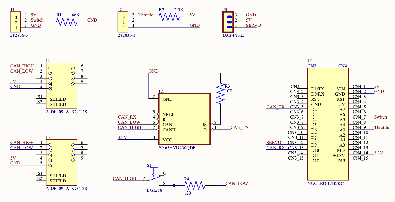
Figure 1: Schematic of Throttle by Wire

Figure 2: PCB of Throttle by Wire
Code Structure Overview
Introduction Embedded within an STM32 microcontroller, the software drives the throttle-by-wire subsystem of a vehicle. It processes throttle commands and motor directions from the CAN bus, computes vehicle speed, and returns this data on the CAN network. The system also generates a PWM signal for motor speed control, utilizing a plethora of hardware components including GPIOs, USART2 for serial communication, CAN1 for network communication, and multiple timers.
Initialization The code’s preliminary segment initializes the system clock and vital hardware peripherals - USART2, CAN1, and timers like TIM1, TIM6, TIM7, and TIM16. These peripherals, once initialized, play a pivotal role in the system’s functionality, overseeing communication and timing tasks.
Key Variable and Structures A plethora of structures and variables are instantiated to facilitate CAN communication (
CAN_TxHeaderTypeDef,CAN_RxHeaderTypeDef), UART communication (huart2), CAN network management (hcan1), and timer handling (htim1,htim6,htim7, andhtim16). Additionally, certain variables retain values pertaining to motor direction, throttle magnitude, speed sensor readings, and computed speeds.CAN Reception and Processing The
HAL_CAN_RxFifo0MsgPendingCallbackfunction, acting as an interrupt handler, is invoked when a fresh CAN message arrives. Within this handler, the throttle magnitude and motor direction are derived from the incoming CAN data.Timer Callbacks and Operations The
HAL_TIM_PeriodElapsedCallbackfunction is activated upon the lapse of a timer duration. Depending on the timer instance, operations like motor speed modulation via PWM, speed sensor reading capture, or speed computation and CAN transmission are performed.UART Write Function Primarily for debugging, the
_writefunction supplants the default write function, enabling UART2 data transmission.System Clock Configuration The system clock configuration resides within the
SystemClock_Configfunction, typically autogenerated by STM32CubeMX.CAN Initialization The
MX_CAN1_Initfunction orchestrates CAN bus setup, defining parameters such as DLC, Identifier types, Frame types, and more.